
How to change 3D Touch Sensitivity in iOS 10: Uninstalling Apps Easily


Uninstalling an application from your iPhone was an easy task until the introduction of "3D Touch" property with iPhone 6s. Although 3D Touch property is very useful and practical, it appeared as a burden for iUsers when uninstalling applications from their phones. 

As most of iPhone users know that to uninstall an app, you need to be able to long press on the application icon. After the introduction of 3D Touch, your tap on the icon might also mean to iOS as a firm press instead of a long press. Then, instead of cross signs to uninstall the app, you will face with pop up option menu related with firm press.

What you should do is simply change the sensitivity of 3D Touch sensors located just below the screen.

Here is the steps for changing the sensitivity of 3D touch sensors:

1- Tap on "Settings" app.


2- Tap on "General".


3- Tap on "Accessibility".


4- Tap on "3D Touch".


5- Here, you can change the 3D TOUCH SENSITIVITY to "Light, Medium, Firm" options. If you encounter problem with uninstalling apps, then you should definitely increase the level from where currently it is.
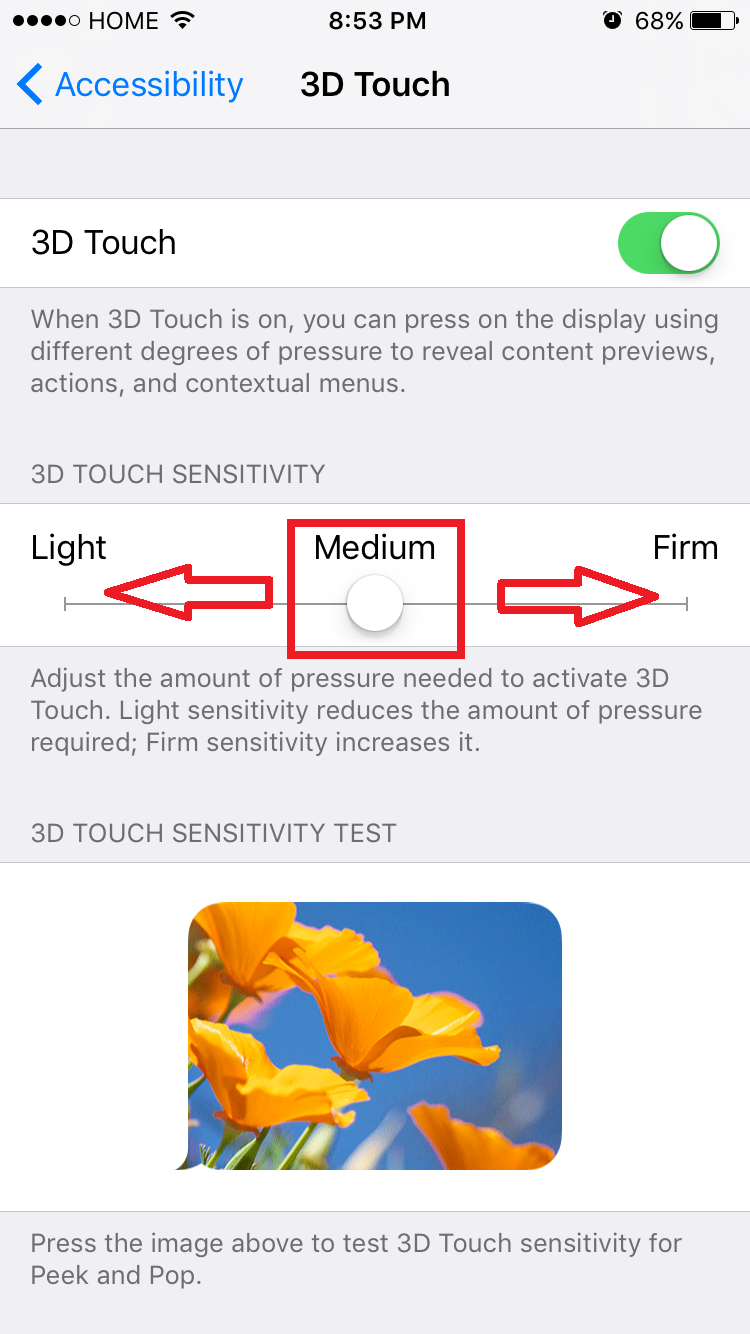

If you don't want to use 3D Touch sensors anymore, you can easily switch off this property.


After switching off, the same screen will be displayed as follows: 


If you ask me, I definitely advise anyone to use 3D Touch property of your iPhone.

NOTE: This is tested on iOS 10.2.1


Comments

Popular posts from this blog

Star Wars ASCIImation with Python - Windows

In this post, we'll watch a Star Wars movie in ASCII format. The only thing we need for this demo is Python-installed PC and internet connection. Figure : Screenshots from Python Command line while Star Wars is being streamed All credits gained in this demo will go to " blinkenlights.nl " [2] website, which broadcasts this ASCII movie using Telnet protocol on Port 23, and Python which makes socket implementation very easy for us. No authentication is needed for this broadcast. Anyone who is able to create a TCP socket and listens  blinkenlights.nl  on port 23 would be able to get this stream and display on their Python command line. CODE My main source for Python source code is [1]. What  code below does is simply importing Python "socket" library, create a socket, use " towel.blinkenlights.nl " address variable to create connection, receive data from socket and display it. While typing (copy/paste) code, be careful about indentatio...

How to Fill out a Cheque?

In this post, I will demonstrate how to fill out a cheque properly. You can have a cheque book either from your bank or any store. If you find these two suggestions expensive, you could also design and print out your own cheque. In Figure 1, a sample cheque is displayed and in Figure 2, some regions of the sample cheque are highlighted. Figure 1: Sample unfilled cheque. Figure 2: Some regions are highlighted in sample cheque. 1- Name and Address of Payer: Name and  address of the person who is the owner of this cheque and is filling out the cheque should be written in this region. 2- Date: For any official document, date is a mandatory field and hence you should write current date in this region. 3- Payee Name: Payee could be either a person or an organization (Store, Restaurant, Company, School etc.) You should write the name of the payee here explicitly. 4- Amount of Payment (Numeric): Exact amount of the payment should ...

ESP8266 Mini Project: GPIO with Button and LEDs

In this post, I'll be sharing a mini project of mine, again using ESP 8266 NodeMCU chip and MicroPython. This project mainly focuses on GPIO pins and methods for this chip. LEDs will be my output and I'll use a button as an Input. My input button will be used as a Start/Stop command for ongoing operation. Ongoing operation will be blinking of LEDs with varying frequency. I'll implement this project in two different methods: Using Asynchronous Polling Using Interrupt Request Setting Up Circuitry GPIO 16, GPIO 5, GPIO 4, GPIO 0, GPIO 2, GPIO 14 pins will be configured as Output pins being pin_D0, pin_D1, pin_D2, pin_D3, pin_D4, pin_D5 respectively. GPIO 12 will be configured as Input pin and will be connected to a small button circuitry. Button simply behaves as a switch and default position is OPEN (no contact between side pins). By default, logic LOW (0) is applied to input pin, when button is pressed (switch is closed) logic HIGH...